Configuration Space Representation
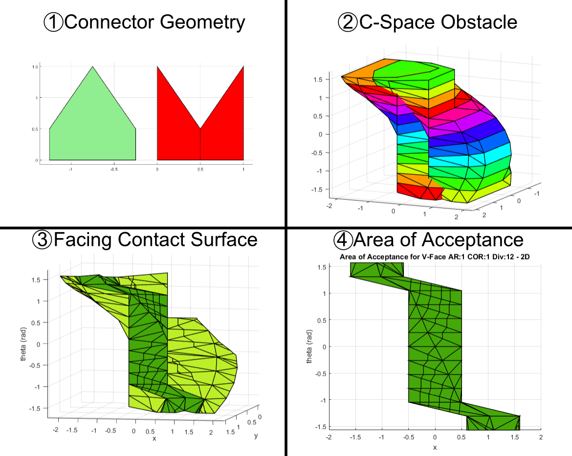
The configuration space is a well-understood method from path planning to represent a robot in the presence of obstacles. Using the Minkowski difference operation, we can ‘grow’ the obstacles according to the geometry of the robot. This creates a new set of obstacles in a space where the robot can be represented as a point rather than a shape. We model our two connectors as ‘robot’ and ‘obstacle’ in this configuration space and generate the corresponding ‘configuration space obstacle’. The outer surface boundary of this space is all configurations in which the two connectors are in contact, and we can perform analysis on this surface to find the ways the connectors will passively align.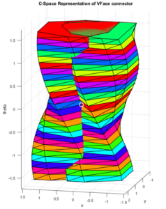
Watershed Analysis
We assume the connectors are being driven towards each other by the robot in a single driven direction, with other degrees of freedom free for the connectors to move. For a pair of 2D connectors this means traveling towards each other in y, with freedom of movement in x and theta (the single rotational degree of freedom)
We now need to find the set of all points whose path ends at the target docked configuration. If the system has a non-trivial AA, the target docked configuration will be at a local minimum and there will be a neighborhood of connected areas that flow to this minimum. For example, in Fig. 3 a configuration space obstacle is shown for the V-Face connector. The target docked configuration indicated with a white circle is at a minimum in Y on the surface. The set of points for which water droplets would flow to this minimum is termed a watershed
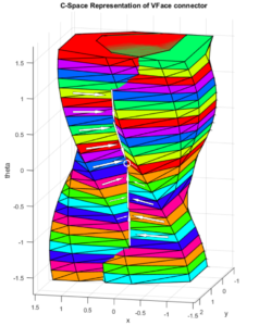
Our watershed algorithm carefully partitions the relevant surface polyhedra so that each has no more than one ‘downhill’ polyhedron. This allows us to transform the surface into a directed graph for characterization. With the graph in hand it is relatively easy to determine which polyhedra ‘flow’ to the target docked configuration, and then find an area for the region that results in docking.
Results
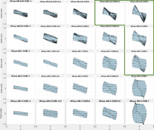
Once the area on the surface that converges to the target configuration is found, we flatten this area down to the plane and find the total area of the region. This area (which we call area of acceptance or AA) serves as a metric we can use to compare any given pair of connectors. Two different connector pair shapes were studied across two design parameters (center of rotation COR, and aspect ratio AR). The two shapes examined were the X-Face and V-Face shapes, which have been examined previously.
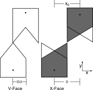
Intuitively, the X-Face should provide a larger area of acceptance for all parameter combinations. However, our results show that for 4 of the parameter combinations tested, the V-Face area was actually larger. This information is potentially useful for robotic designers who may wish to build these shapes on robots with similar parameters, as it will allow easier docking under uncertainty.

Conclusion
We have introduced a new method of analysis for the area of acceptance of mechanical connectors under alignment. The method makes use of the configuration space obstacle representation of the connector pair and a new watershed determination method to find the region of attraction also known as the area of acceptance. The result is a metric we can use to compare the connectors and their range of acceptance. This information allows us to make informed decisions about connector design parameters in robotic contexts.
-
![[PDF]](https://www.modlabupenn.org/wp-content/plugins/papercite/img/pdf.png) N. Eckenstein and M. Yim, “Modular robot connector area of acceptance from configuration space obstacles,” in 2017 ieee/rsj international conference on intelligent robots and systems (iros), Vancouver, Canada, 2017.
N. Eckenstein and M. Yim, “Modular robot connector area of acceptance from configuration space obstacles,” in 2017 ieee/rsj international conference on intelligent robots and systems (iros), Vancouver, Canada, 2017.
[Bibtex]@inproceedings{NE:MY:17, title = {Modular Robot Connector Area of Acceptance from Configuration Space Obstacles}, author = {Eckenstein, Nick and Yim, Mark}, booktitle = {2017 IEEE/RSJ International Conference on Intelligent Robots and Systems (IROS)}, address = {Vancouver, Canada}, year = {2017}, pdf={https://www.modlabupenn.org/wp-content/uploads/2017/10/2017_Modular_Robot_Connector_Area_of_Acceptance_from_Configuration_Space_Obstacles.pdf} }
Pingback:ModLab UPenn » Archive » High-Dimensional Modular Connector Area of Acceptance Using Discrete Configuration Space Methods